 |
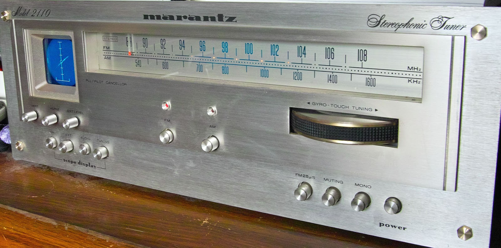
| Figure 1: The Marantz 2110 with the now-functioning scope. Click on the image for a larger version. |
The 2110 is a medium-to-high end FM/AM broadcast receiver from the early/mid 1970's and it is equipped with a small oscilloscope for a tuning aid as much as "ooh's and ahhs." It had been given to me in a semi-non-working condition by a friend of mine a few years before and all it really needed at the time was a thorough re-alignment and a cleaning of switches and it was back in working order.
In addition to the 'scope having an external X/Y input to set the phasing of external audio gear (e.g. tape recorders, etc.) this receiver will also show two-channel stereo (or mono) audio with the 'scope's X/Y channels being fed by the tuner's own two audio channels: On mono broadcasts, a diagonal line of varying lengths is displayed, slanting from upper-right to lower-left (as can be seen in the above photo) and with stereo reception one sees a semi-random field of lines with the same general slant: If, somehow, the phase of one channel were reversed, the slant of the line would also be reversed (top-left to bottom-right.)
For tuning, the 'scope display is a bit different: On AM, a short horizontal line simply goes up and down, the vertical height being related to the signal strength. On FM, the horizontal position of a short vertical bar (with respect to the center) represents how well the signal is tuned: If the small bar is to the left, the tuning dial is low in frequency and vice-versa if it's high. The vertical position of the small bar also indicates signal strength of FM, but it also indicates something else: It will show residual AM, and the more of this, the longer this bar will get.
Recall the difference between AM and FM: On the latter, the signal strength does not change with the audio - or at least it shouldn't! If it does, this might be a result of one or both of the following:
- Mistuning of the signal puts a portion of it partway off-frequency. In that case, as the FM signal wobbles up and down in frequency with audio, part of it may go outside the receiver's filter so less is intercepted, the result being that the signal level as "seen" by the receiver changes.
- Multi-path distortion. If there are multiple reflections of a signal due to buildings, mountains, etc. the signal strength of multiple reflections can either reinforce each other or cancel each other out. As it happens, these effects can be frequency-sensitive and wobbling of the frequency up and down with audio modulation can cause the varying reinforcement/cancellation and also affect the signal strength at the receiver.
So, on FM, the scope is most useful for making sure that the receiver is tuned in the dead center of the received signal - especially important since this receiver doesn't have an AFC - Automatic Frequency Control - to "lock" it on frequency to compensate for the inevitable drift as it warms up.
Back to the 'scope.
But first:
The obligatory warning about high voltage:
The voltages found in this receiver - particularly those around the mains power supply and the oscilloscope - are potentially lethal!!!
If you aren't familiar with the safety precautions and techniques related to high voltages
If you aren't familiar with the safety precautions and techniques related to high voltages
you have NO BUSINESS messing with them!
Before final replacement of the transformer, check the high-voltage capacitors and diodes to make sure that they are in good shape - possibly preemptively replacing them: It may have been a failure of one of these components that caused the original transformer to fail. If you are really lucky, one of these components failed and the transformer may be fine!
I can take no responsibility for any damage or injury that might result from anyone attempting to use the techniques described on this page! While these techniques may be applicable to other tuners/devices with built-in oscilloscopes, you are on your own to do the necessary legwork to determine that device's requirements!
When the scope flickered out for good I popped the cover off the receiver and wielding a voltmeter and a somewhat fuzzy copy of the service manual that I'd found online I was chagrined to note that all of the several voltages coming out of the scope's power supply transformer were missing, indicating that the primary winding had failed open: Unsoldering of the relevant primary wires for the transformer and a subsequent ohmmeter check verified this.
I could have probably come up with some sort of modern switching supply circuit to generate the needed voltage - possibly from a something found on EvilBay - but these sorts of voltage converter modules all have one thing in common: They produce fairly high amounts of electrical noise at ultrasonic frequencies. From past experience I knew that if I put one of these devices inside the tuner it would be nearly impossible to keep it from getting into the receiver's other circuits and causing some sort of interference - particularly the AM tuner! (I don't use the AM tuner much, but still...)
After using the receiver "scopeless" for over a year I decided to see what I could do to effect a replacement so I removed the dead transformer and did a bit of research and found that, as expected, it was a common item to fail and a direct replacement was essentially unobtainable. In disassembling the transformer far enough to determine that not only had the "inner" connection of the primary winding failed, I also determined that I wasn't going to get the transformer apart far enough to rewind the primary without damaging the other windings.
 |
| Figure 2: A re-drawn portion of the original Marantz's Scope Power Supply Wiring. The fuses on the power supply board are not shown. Click on the image for a larger version. |
If I wanted the 'scope to work again, I'd need to find a replacement of sorts!
According to the service manual, what I ultimately needed were the following (nominal) DC voltages as best as I could discern from the fuzzy drawing:
- -601 volts for the CRT's cathode.
- +186 volts for the vertical and horizontal deflection amplifiers.
- 6.4 volts AC for the CRT's filament, and this winding had to be isolated so that it could "lifted" to the -601 volt CRT cathode potential.
In looking online at a number of different transformers I ordered a possible replacement from Antique Electronics Supply: Not an exact replacement, mind you, but one that could have been made to work - but it turns out that I should have looked in my own transformer collection first!
When I looked in my "box o' transformers" I found that I had a several Thordarson T-63041-1CB transformers in my collection that I'd acquired at some point in the unknown past and although I have yet to find official specifications for this device on the web, I also discovered, in the same box with the transformers, a note detailing what I had found several years before when I'd reverse-engineered it using an ohmmeter to determine the likely windings and then the careful application of AC voltages through a "Variac" (tm) type autotransformer. Based on what few specifications were on the transformer's label (e.g. its primary voltages) I was able to figure how to safely apply power to its primaries (it has two!) and then measure the secondary voltages. As it so happens it had not only an isolated secondary that measured 6.6 volts (unloaded!) but also one that measured 180 volts.
Figuring that I could make something of this transformer, I set to work!
 |
| Figure 3: The transformer used as a "replacement". Most importantly, it has an isolated 6-ish volt filament winding! Click on the image for a larger version. |
This transformer was slightly smaller in height and width than the original, and a millimeter or so "thicker" but it looked as though I could cram it in the original transformer's metal casing.
First, I drilled a hole one of the original transformer's side (called the "bell") covers (and filed it to smooth the sharp edges) to allow access to the secondary winding's wires as this transformer had wires coming out of both sides of the winding face instead of the front and back as per the original. I then centered the transformer in the original side covers and was able to "gently force" the transformer into the U-shaped mounting bracket after bending it to accommodate the slightly thicker transformer. Holding everything in a vise, I was able to attach the bottom cover and bend the original cover's tabs into place, using a screwdriver to align them and when I was done, the "new" transformer didn't look much different from the original! Using the original case - and its implied shielding - is often important as it prevents the magnetic field from the transformer from affecting the trace of the oscilloscope!
Now, to make both +186 volts and -601 volts out of a single 180 volt winding!
As we can see from the drawing in figure 2, individual windings - all referenced from the center-tap - were used on the original transformer to produce the high voltages. In this case, a pair of 166 volt windings, center-tapped, were used to full-wave rectify and produce the nominal +186 volt DC supply for the scope's deflection circuits. On one side of the center tap we also see a 430 volt winding that was half-wave rectified to produce the -601 volt which was then filtered by a series pair of 10uF, 350 volt capacitors - and this voltage was applied to the floating 6.4 volt filament windings.
 |
| Figure 4: The diagram of a diode-capacitor tripler to increase the voltage of a 180 volt AC winding to produce the negative CRT Cathode voltage. The two capacitors on the left can be 1uF at 450 volts - enough for the low-current CRT beam supply. The diodes are 1N4007 types. The capacitor on the right is representative a capacitor in the original circuit. Click on the image for a larger version. |
Fortunately, there's nothing here that overly complicates the ability to generate these same voltages via an alternate means, and as it turns out we can use our new-found transformer's 180 volt winding to generate both of these these voltages. Generating the +186 volt supply is trivial: Simply ground one end of the 180 volt winding and half-wave rectify it - and this produces roughly +180 volts DC, just what we need! See figure 5.
Generating the -601 volt supply is a bit trickier - but not overly so: By using a small assortment of capacitors and diodes we can take that 180 volt AC waveform and multiply it several times to produce the desired voltage. In this case, we use a voltage "tripler" which takes advantage of the peak voltage of the 180 volt winding so that the actual "AC-Input to DC-output" voltage ratio is closer to 3.8 than 3 and this just happens to yield a voltage very close to our nominal -601 volts, or around -615 volts (under circuit load) as depicted in the drawing above. To our advantage, we need very little current to supply the CRT's cathode which allows us to use rather small-value (1 uF) capacitors as depicted below.
As it happens, some of the circuitry required for a tripler is already included in the original Marantz power supply, namely the last diode and capacitor on the far right of figure 4 and this means that we don't need to build all of the circuity above (but if we did, it wouldn't hurt...) so we end up with the final schematic shown in figure 5.
 |
| Figure 5: Alternate power supply for the Marantz scope. The portion in the box is the "external" diodes and capacitors that we will mount in heat-shrink tubing and connect to the Marantz power supply board. Note that the "ground" inside the box also connects to J816. Click on the image for a larger version. |
As seen in the drawing the filament supply connects to J819/J820 in the same manner as the original since we have the same "floating filament" winding arrangement as the original transformer. We don't have a center-tapped transformer, so we simply connect one end of the 180 volt winding to the system ground (J816) while the other end of the transformer connects to either J815 or J817 (or both, if you really want) but it doesn't matter which, since we are using a half-wave rectified circuit instead of the original center-tapped full-wave!
Even though our new transformer's winding produces 180 volts AC instead the 166 volts AC of the original, our DC voltage is ultimately about the same due to the half-wave rectification. Our power supply is still "clean enough" in terms of AC ripple since the capacitance on the original power supply board (10uF) is more than adequate.
 |
| Figure 6: The added circuit, consisting of two 1uF/450 volt capacitors and two 1N4007 diodes is shown connected, floating in space on their connecting wires before being enclosed in heat-shrink tubing. Click on the image for a larger version. |
In figure 6 we can see these components assembled, hanging in free space on the wires - along with insulating tubing on the component leads - connected into the circuit. If you look carefully at both the picture and the drawing above you'll note that it connects in only three places:
- The "ground" (bottom of the capacitor in the box) goes to J816 - the main system ground..
- The "input" (180 volts AC) goes to J815 and/or J817 - the same terminal that the "top" of the 180 volt winding was connected.
- The "output" of the circuit connects to J818 where the original 430 volt winding connected.
I measured about +175 volts where +186 volts should have been (close enough!) and -617 volts where -601 volts was to be (pin 1 or 2 of J914). It's worth mentioning that if you measure the voltage at J818, you won't see the -600-ish volts since the rest of the multiplier circuit (e.g. the last diode and capacitor) is on the board, which is why you'll see the -600-ish volts only at J914! Carefully measuring the filament voltage (which is at -600 volts with respect to the chassis!) I observed 6.3 volts or so - a slight drop from the "unloaded" 6.6 volts measured above and just perfect for the CRT filament!
To complete the circuit I added a bit of extra insulation to some of the wires connecting the capacitors and diodes (I used some craft paper, taped together) so that they could not touch when the piece of heat shrink tubing that was slid over the above was shrunk, compressing components and leads together. Finally, the module was completely enclosed in shrink tubing and attached to the brown wire from J914 with a single nylon wire tie to keep it in place as can be seen in figure 6.
Taking my own advice, I also checked the two 10 uF, 350 volt series-connected capacitors that filtered the -601 volt supply. When powering up, I (carefully) measured the voltage across each capacitor and while half the power supply voltage should have been across each capacitor, I noticed that there was about 400 volts across one and 200 volts across the other indicating that at least one of them had a problem! Unsoldering them from the board (after first having disconnected the power and shorting them out to discharge the remaining voltage!) I noticed a small amount of crust on the board as well as some corrosion around the capacitors' leads indicating that they were leaking electrolyte.
 |
| Figure 6: The circuit in heat-shrink tubing, installed. The "new" transformer is the one in the background, on the left. If you look carefully you can see the new hole where the secondary's wires emerge. Using the original transformer's case, it was nearly a perfect fit! Click on the image for a larger version. |
After replacing them with a pair of 33uF, 400 volt units I saw that the voltages across each capacitor were within 10-20 volts of each other. Practically speaking, a capacitor value as low as 1 uF would probably suffice, but all I had in that voltage range were the 33uF units mentioned. These two capacitors, when replaced, should be identical and from the same batch, if possible. Normally, high-resistance (330k-680k) resistors are placed across series-connected capacitors to equalize the voltage, but that was not done in this case: Next time I have the receiver apart I will add those to the bottom of the board - just to be safe!
Running the receiver for several hours I observed that the transformer doesn't get any warmer than the ambient temperature within the receiver itself. I seem to recall that the original transformer ran a bit warm indicating that it was either already somewhat faulty or, more likely, that it had originally been under-designed with too-few turns on its primary and causing it to run a bit warm (a cost-savings measure, no doubt!) and possibly leading to its ultimate failure.
Replicating the repair for your gear:
It was serendipity that I happened to have a suitable transform on hand - and as noted above, I'd forgotten that I did since I'd already ordered (and received) a potential candidate device from Antique Electronics Supply (with a 250 volt AC secondary) in retrospect, it would have been a bit more complicated to make it work as I'd have had to reduce the voltage somehow to get the needed +186-ish volts, so I'm actually happier with the way things actually worked out. (Now I have this "other" transformer sitting around, waiting for a project of some kind...)
The tricky part is finding an appropriate transformer! While these sorts of transformers used to be common in the "tube" days, they are increasingly difficult to find but similar devices are still made and available from specialty suppliers. Fortunately, a suitable transformer is readily available - for a price: The Hammond P-T269EX. This is a general replacement device available from a number of places (including Antique Electronics Supply) and it's fairly close in specifications to the one that I used. It's size is slightly different, but it should be capable of fitting inside the '2110 cabinet some modification and adaptation - but it's up to you to do read the specifications and do the measurements to make sure!
The main difference between it and the transformer that I used is that the P-T269EX has a 190 volt center-tapped winding (e.g. 190-0-190) in addition to a 6.3 volt 2.5 amp winding which is suitable for the filament supply of the CRT. In this case, you'd use only half of the secondary (only the center tap to ground and one of the 190 volt end-windings) as connecting it in the same manner as the original (e.g. the full-wave rectification) would bump the deflection circuit voltage up well above 200 volts - probably a bit too high for our purposes: As it is, the 190 volts (instead of 180 volts of the above transformer) with the half-wave rectification will increase the voltage somewhat: As long as its below about 200 volts, it should be fine.
Running the numbers you'll note that instead of the -615 volts or so that I obtained with the 180 volt winding, with the 190 volt winding you'll get closer to -650 volts - but this should be well within the operational range of the CRT.
Another possible source of transformers is Edcor (main web site: http://www.edcorusa.com ) and their model number XPWR058-120/240 (link: http://www.edcorusa.com/p/652/xpwr058_120 ) looks like it should work using half of the low-voltage secondary to get 6.3 volts. Please note that I've not used this transformer nor verified that it will fit in the available space within the receiver.
If you can't find a single transformer with the necessary voltages it should also be possible to use a number of different transformers to make such a 'scope operational again - provided that one can find somewhere to mount them in the receiver chassis! One could take practically any transformer with a "medium-voltage" secondary (90-190 volts) and using similar voltage multiplication techniques, bump up the voltage(s) to that (those) required. The good news is that a 6.3 volt transformer is readily available and one should be able to find something that should be able to produce anywhere from +150 to +200 volts for the deflection circuit - and anywhere from -500 to -650 volts for the CRT's cathode - anything in that range being able to give reasonable results. If there's any critical voltage in this circuit, it's that the CRT's filament voltage should be as close to 6.3 volts as possible!
Note that with a smaller/larger number of diodes and capacitors, one could also produce different multiplication factors of DC voltages, potentially taking advantage of a wider variety of transformers that might be found. The topology shown in the above circuit has the obvious advantage in that one end of the 180 volt secondary is grounded and this easily allows both positive and negative voltages to be produced from the same winding.
If, when the appropriate circuits are applied, one or both of the higher voltages turn out to be a bit too "high", one could always resort to dropping resistors to tame them: The CRT itself takes only a tiny amount of the -600 volt cathode current - and it's the most forgiving in terms what voltage range will work. What should be remembered is that dropping resistors generate heat and it's best that this be kept to a minimum - or at least as far away from the "front end" circuit as possible to minimize thermal drift of the FM receiver during operation.
Comment:
For 120 volt mains, it's quite common to find transformers with "split" primaries that are connected in series to allow 240 volt operation. If the transformer is lightly loaded - as it would be if it were used to supply just the +180 and -601 volt supplies, the "extra" primary winding may be used to provide about 120 volts AC and appropriately configured and multiplied, should yield voltages that would adequately operate the scope. It may be possible to find a "split-primary" 6.3 volt transformer that will power the filament, but remember that if you use just one of the primaries, you should derate the transformer to no more than 40% or so of its original power rating!
Final words:
Again, it should be reiterated that the voltages used by these and other circuits within the receiver are potentially lethal and that anyone considering dealing with them should be well experienced in such voltages and take the appropriate precautions.
Also remember to check the diodes and capacitors of the original circuit to make sure that they are in good shape as it may have been a failure of those components that took out the original transformer!
It's entirely possible that these techniques are applicable to other models and makes of equipment that use a similar oscilloscope module, but you should do your own legwork and research to determine what is required - and if in doubt, seek help from someone who knows about these things!
Before you ask:
- No, I won't fix your receiver - sorry: There appear to be others (findable with a search engine) that do work on this type of gear to the extent that spare parts are available.
- I happen to have a couple of extra Thordarson T-63041-1CB transformers kicking around (at the time of this writing) with which I may be convinced to part.
- I've not found any "official" data for the CRT used in this receiver (e.g. the Hitachi 50TB31) but it would appear that the filament voltage is the standard 6.3 volts. The cathode voltage noted on the diagram (e.g. -601 volts) is quite typical for a small-ish (e.g. 2") CRT.
- And no, I have no idea where one might get a "new" CRT should the one in your receiver be bad - sorry - but make certain that there's nothing wrong with the 'scope's power supply before you condemn it!
- Other Marantz solid state receivers (e.g. the 2130, 2500, 2600 and 4400 series, etc.) may use the same/similar CRT (display tube) and similar power supply transformer arrangements, but I don't have personal experience with any of these other tuners!
[End]
This page stolen from ka7oei.blogspot.com
This was really cool! I also have a 2130, had it since about 1977 as part of my dad's collection. Haven't powered it up in years, but, it I do remember it did have an intermittent connections somewhere which would cause only the display to show everything as mono, meaning no cotton ball type stereo images. As a kid, if I smacked it a little with my palm, it'd start working correct again. Took it to a repair shop back in the late 70's, but the guy could find nothing wrong..but don't know how hard he looked, or his knowledge base.
ReplyDeleteThere is a good chance that it it wasn't running stereo unless slapped - which could be caused by a lot of things, but I'm pretty sure that someone would have noticed that the stereo light (which burns out easily) would have gone off/on. From what I recall of the signal path the only real thing that could have caused what you saw in the 'scope circuit would have been the front-panel switch itself.
DeleteBest of luck in resurrecting the 'scope and receiver!
I was also an audiophile since about 12 yrs old (1974), and I do remember it must have been the front panel switch then, because it for sure was outputing stereo as I could hear it wasn't mono, and I don't remember the stereo light being off when it happened.
ReplyDeleteHowever, while I do remember the that for sure, it is possible that I'm off on my memory or what the scope would do...perhaps it wasn't a straight line, but perhaps instead it collapsed completely into a point. And perhaps I should fire it up again and find out!
By the way, I do have the service manual if you are interested. Dave
ReplyDeleteI know that I was able to dig up the schematic diagram to help determine the needed voltage for the 'scope - but I don't recall offhand if I have all of the service documentation as well.
DeleteI'll try to rummage around and see if I have it - but if not, I'll let you know - Thanks!